
From Point Cloud to an Aligned, Editable CAD Solid
Point2Solid Studio has reached an important stage in development. We can now take scan-derived geometry through recognition, engineering datum creation, origin and model alignment, and into a BRep STEP file that can be opened and edited directly in CAD software such as Fusion and SolidWorks.
A major step towards a practical scan-to-CAD workflow
When we began developing Point2Solid Studio, the aim was never simply to convert one 3D file format into another.
A scanner can give you an excellent point cloud or mesh, but for engineering and reverse-engineering work that is often only the beginning. The useful result is geometry that has been recognised, positioned around meaningful engineering datums and transferred into CAD in a form that can actually be worked with.
The latest development builds are bringing those stages together inside a single workflow.
1. Engineering geometry can now be detected from the scan
The Geometry & Datum Studio is becoming the engineering centre of Point2Solid Studio. Instead of treating the imported model as nothing more than a large collection of triangles, the software analyses the scan-derived surface and looks for useful engineering features.
These include planar surfaces, cylinders, bores, radii and other regions that can become reference geometry for later alignment and datum construction.
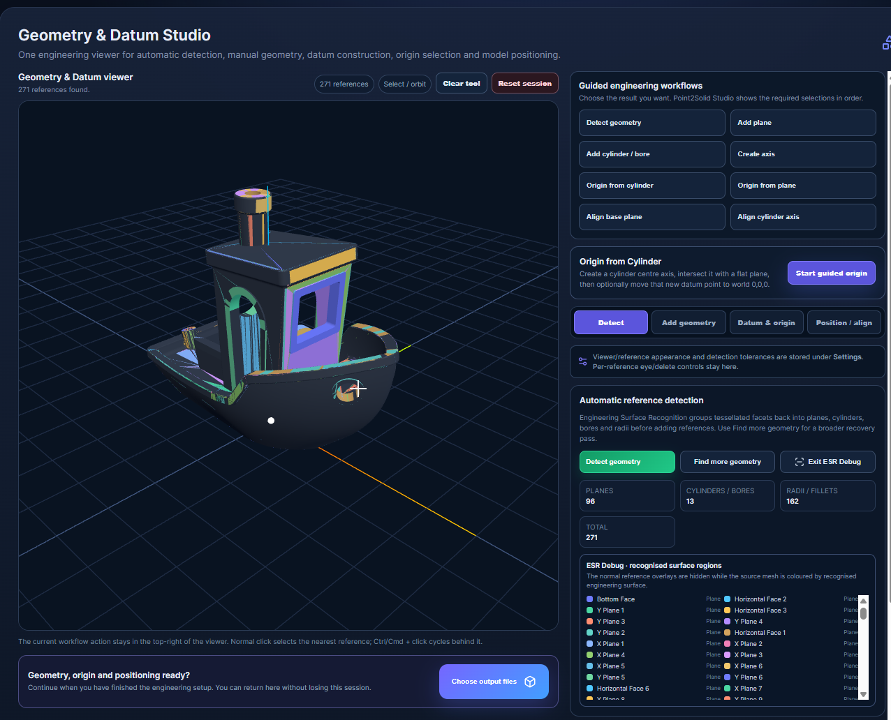
Why this matters: a useful CAD workflow needs more than a visually accurate scan. We need to identify the planes, cylindrical features and other geometry that represent how the component would actually be measured, aligned or manufactured.
2. Detected geometry becomes usable engineering references
Once geometry has been recognised, Point2Solid Studio can create engineering references from those regions. These references can then be selected for origin creation, axis definition, plane alignment and model positioning.
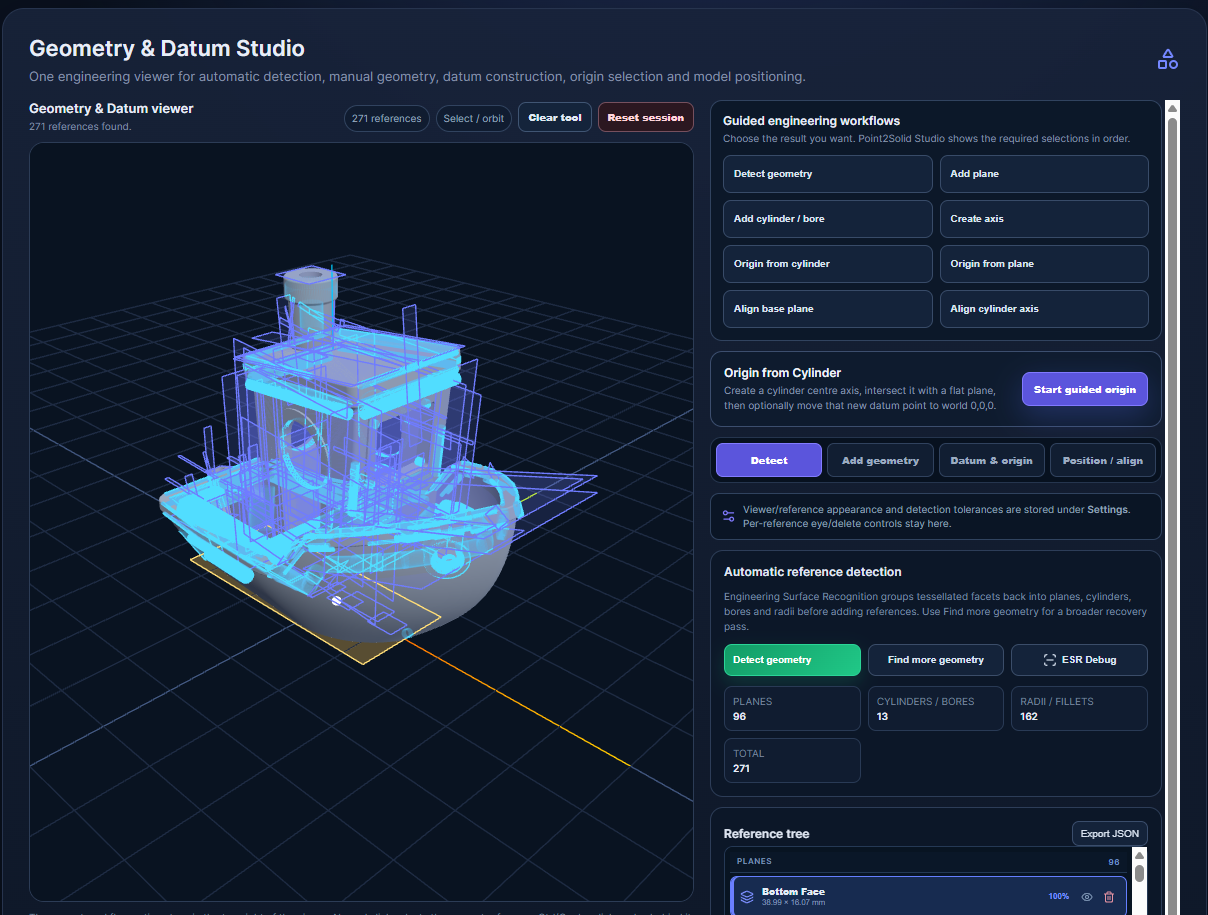
The current system includes both automatic detection and guided engineering workflows. For example, an origin can be built from a cylindrical centre axis intersecting with a selected plane, or a base plane can be used to orient the model.
3. Origin and alignment can be established before export
One of the most important parts of reverse engineering is deciding where the model belongs in space.
A scan may be geometrically accurate but arrive at an arbitrary angle and position. That is not ideal when the result needs to enter a CAD assembly, match an existing coordinate system or be measured from known engineering datums.
Point2Solid Studio can now use the selected reference geometry to establish the model origin and align the reconstructed geometry to the world coordinate system before creating the CAD output.
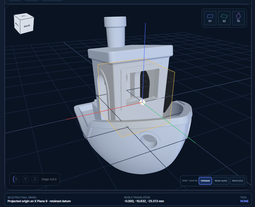
Select engineering geometry
Use detected planes, cylindrical features and other references from the scan.
Create the datum
Establish planes, axes and an origin based on meaningful features of the scanned component.
Align the model
Transform the reconstructed geometry into the desired engineering coordinate system.
Export to CAD
Generate the BRep STEP model with its origin and orientation already established.
4. The result is now a genuine BRep STEP model
This is the part of the project we are particularly pleased to see working.
Instead of finishing with a triangle mesh wrapped inside a STEP container, Point2Solid Studio can reconstruct the model as boundary-representation geometry — BRep.
That distinction is important. BRep geometry is made from proper CAD faces, edges and solid bodies. It gives CAD software something fundamentally more useful than the original scan mesh.
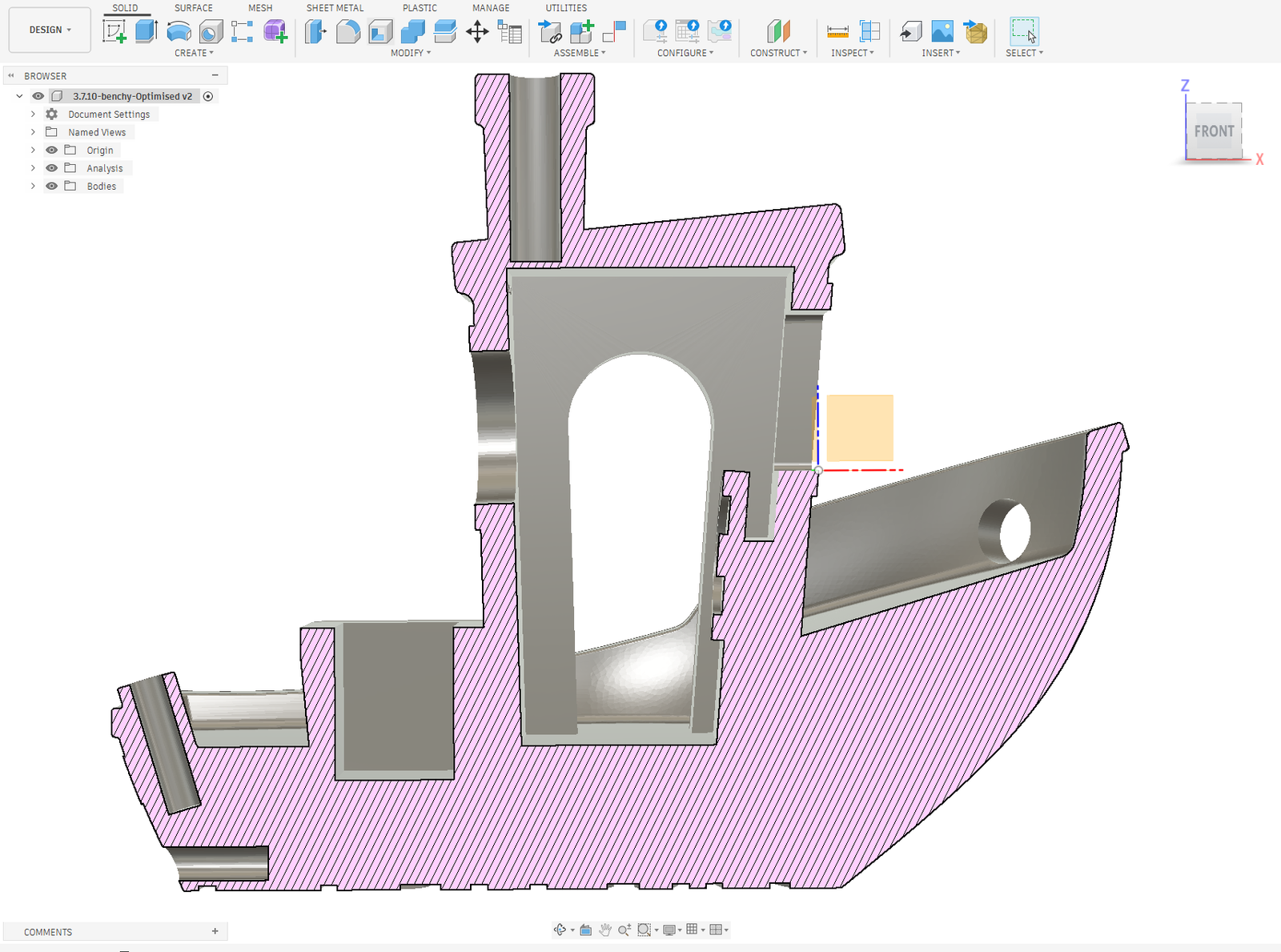
The important result: the STEP file can be brought directly into a conventional CAD environment and treated as CAD geometry rather than simply being used as a visual mesh reference.
5. Directly usable inside CAD
The reconstructed Benchy test model below has been opened in Autodesk Fusion as a BRep solid after processing through Point2Solid Studio.
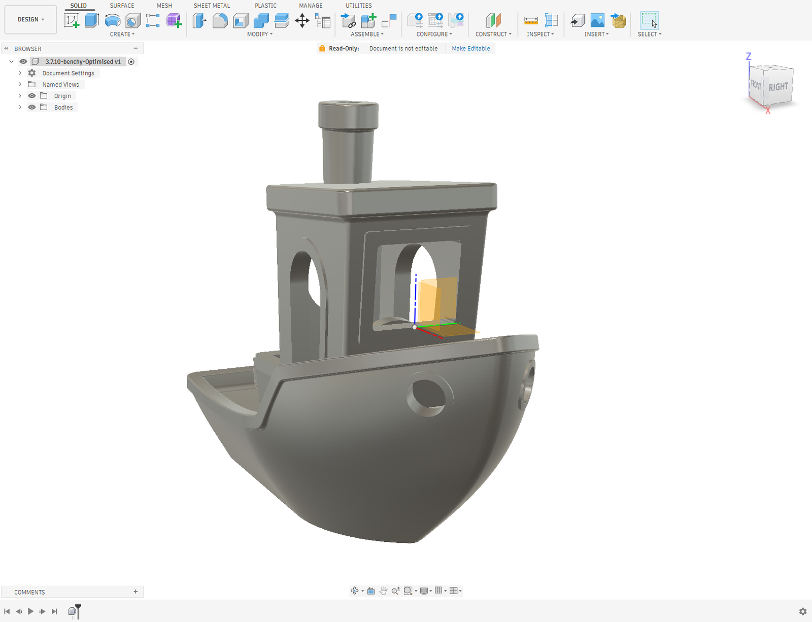
This opens the door to the part of the workflow that originally motivated Point2Solid Studio: taking real-world scanned geometry and making it practical for reverse engineering.
- Import scan-derived point-cloud and mesh data.
- Recognise useful engineering geometry.
- Create planes, axes and datum references.
- Establish a meaningful engineering origin.
- Align and reposition the model.
- Reconstruct the geometry into BRep.
- Export a STEP file for continued work in CAD.
What this changes for the project
Until now, a lot of the development work has necessarily been focused on individual pieces of the problem: importing data, processing meshes, identifying geometry, reconstructing surfaces, creating STEP files and establishing an engineering coordinate system.
We are now reaching the stage where those pieces are beginning to operate as one connected workflow.
There is still plenty to develop and refine. Surface recognition needs to cope with a wider range of real-world scans, reconstruction needs to continue improving, and the engineering workflows need to become as quick and intuitive as possible.
But the important foundation is now visible: we can start with scan-derived data and finish with an aligned BRep solid that can continue its life inside a normal CAD package.
Why we are using Benchy during development
The Benchy model makes a useful development test because it combines flat surfaces, curved hull geometry, cylindrical features, holes, internal openings, fillets and intersecting geometry in a compact model.
It lets us repeatedly test the entire pipeline while the underlying technology is being developed.
Point2Solid Studio is not being developed simply to convert Benchy, of course. The objective is practical scan-to-CAD work where a scanned component needs to be reconstructed, aligned and brought into an engineering workflow.
Next stages
Development is continuing rapidly. Some of the areas we will be concentrating on next include:
- Improving automatic engineering surface recognition.
- Refining plane, cylinder, bore and radius detection.
- Making datum and origin creation faster and easier.
- Improving reconstruction quality on real scanned components.
- Reducing unnecessary geometry in the resulting CAD model.
- Continuing STEP/BRep compatibility testing across CAD systems.
- Testing with a wider variety of scanners and scan types.
We will also increasingly move from controlled development models into the sort of practical scanned parts that Point2Solid Studio is ultimately intended to handle.