I thought the hard part was 3D scanning.
Then I tried turning the scan into something I could actually edit in CAD.
Point 2 Solid Studio is being created because, as somebody relatively new to 3D scanning, I discovered a surprisingly large gap between producing a good scan and ending up with a practical, aligned and editable 3D model that can be used for CAD and reverse engineering.
Getting into 3D scanning
My introduction to serious 3D scanning started with the Creality Raptor Pro.
The exciting part
Like most people starting out, I was fascinated by the idea of pointing a scanner at a real component and capturing its shape digitally.
The Raptor Pro can capture an impressive amount of detail, and once you start getting decent scans the obvious next thought is: great — now I can put this into CAD.
Then came the surprise
Getting a point cloud or mesh is only part of the job.
What I wasn’t prepared for was just how awkward the next stage could be: cleaning the data, understanding meshes, dealing with huge files, positioning the scan correctly and eventually trying to turn it into geometry that CAD software can actually work with.
“There seemed to be plenty of information about creating a scan — but far less about what a beginner is supposed to do with it afterwards.”
A point cloud isn’t an editable CAD model
This is the part of the process I think deserves much more attention.
A scanner can give you millions of measured points. Software can turn those points into a mesh. A mesh can look fantastic on screen.
But a good-looking scan is not necessarily an engineering model.
If you want to use that scan for reverse engineering, measurement, modification, manufacturing or design work, you quickly start asking different questions.
The newbie pitfalls
I’m not approaching this project as somebody pretending that 3D scanning and reverse engineering are effortless. Quite the opposite.
Meshes are not solids
One of the first lessons is that an STL, OBJ or PLY file isn’t the same thing as the type of editable solid geometry most CAD users expect.
Alignment matters
A scan may be geometrically accurate but sitting at an inconvenient angle, origin or coordinate system. For engineering work, that becomes important very quickly.
File size gets serious
Detailed scans can contain enormous amounts of geometry. Converting that data without creating impractical files or losing useful detail is a problem in itself.
Automatic isn’t always useful
A conversion can technically succeed and still produce something that isn’t particularly useful when you open it in your CAD package.
Datum comes next
Reverse engineering isn’t just about shape. You eventually need sensible planes, directions, centres, origins and references.
The workflow is fragmented
I found myself testing different applications, formats and conversion methods just to move from one stage to another. That is exactly the workflow I want to simplify.
So I decided to build the tool I wanted
Originally: PINXS Mesh Studio
The project started life under the development name PINXS Mesh Studio.
As the project has developed, it has become clear that it is about much more than simply converting one mesh format into another.
The real objective is the complete journey from scanned geometry to something genuinely useful in an engineering CAD workflow.
Now: Point 2 Solid Studio
The software will now be known as Point 2 Solid Studio.
The name describes exactly where I want the project to go: taking scan and point-based geometry and progressively turning it into aligned, structured and CAD-usable solid geometry.
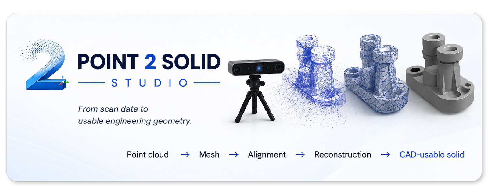
Point cloud → mesh → alignment → reconstruction → solid.
Where Point 2 Solid Studio is now
This isn’t just an idea on a drawing board. Development is already underway, and we’re working through the practical problems one by one.
3D model workspace
Imported geometry can be displayed in an interactive 3D viewer and rotated to inspect the scan.
Mesh processing workflow
We’re building the process for loading and preparing scanned geometry for further conversion.
CAD export experimentation
Several approaches to generating STEP and CAD-compatible output are already being tested against real scan data.
Practical solid reconstruction
Finding the right balance between scan detail, usable CAD geometry, processing time and sensible file sizes.
Alignment and origin tools
Making it easier to orient scanned components around useful engineering planes, axes and datum references.
A workflow normal users can understand
The aim isn’t just clever geometry processing. The software needs to make sense to somebody who is learning this process for the first time too.
Where we want to get to
The finished application should make the journey from scan to usable engineering geometry considerably less intimidating.
Our goal for Point 2 Solid Studio
- Import common 3D scan, point cloud and mesh formats.
- Inspect the model immediately inside an interactive 3D workspace.
- Clean and prepare scanned geometry for conversion.
- Help establish useful planes, axes, centres, origins and datum references.
- Align scans into a sensible engineering coordinate system.
- Reconstruct geometry in a form that CAD software can work with.
- Export practical CAD-compatible files without unnecessarily enormous output.
- Make the workflow understandable for people who aren’t reverse-engineering experts.
We’re going to share the journey
Part of the reason for creating Point2Solid.com is to document what happens while we build the software.
What works
We’ll show the parts of the workflow that are working well and the improvements that make it into new builds.
What doesn’t
Development isn’t always tidy. Failed conversions, oversized files and approaches that don’t work are part of solving the problem too.
What comes next
As features become usable, we’ll explain where the project is heading and what we’re concentrating on next.
Want to follow the build?
Early beta testers will be especially welcome.
As soon as builds reach a stage where they are useful outside my own test environment, I’d like to make early versions available to people who are willing to try them with their own scan data.
Real-world testing will help uncover the things that are difficult to find with a handful of test models — different scanners, different objects, different CAD packages and completely different workflows.
From a real object to something you can actually engineer with.
I’m still learning a lot about 3D scanning myself, and that’s an important part of this project.
Point 2 Solid Studio is being built around the problems I’m encountering while trying to use real scan data for real CAD and reverse-engineering work — including the confusing parts, the failed attempts and the things that initially seem as though they should be much easier than they actually are.
If we can turn those lessons into software that makes the process simpler for the next person starting out, Point 2 Solid Studio will be doing exactly what I want it to do.